Select a spring type
COMPRESSION
SPRINGS
EXTENSION
SPRINGS
TORSION
SPRINGS


Compression spring chosen

This page will give the option of going straight to the calculator, or below will be a list of design options to help define the spring first.

Extension spring chosen

This page will give the option of going straight to the calculator, or below will be a list of design options to help define the spring first.

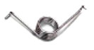
Torsion spring chosen

This page will give the option of going straight to the calculator, or below will be a list of design options to help define the spring first.

Calculation
Stress graph
Drawing
Fatigue
Report
RFQ

Inputs - press ENTER to calculate.

Units
Material
End Type
Wire diameter
UNIT
Outside diameter
UNIT
Total coils
 
Free length
UNIT
Spring rate
UNIT

Operating position 1

Length
UNIT
Deflection
UNIT
Load
UNIT
Stress
% UTS

Operating position 2

Length
UNIT
Deflection
UNIT
Load
UNIT
Stress
% UTS

Outputs

Solid length
UNIT
Solid load
UNIT
Active coils
 
Inside coil diameter
UNIT
Spring index
 
Pitch
UNIT

Drawing

Stress Graph

The spring should not be used for loads corresponding to a deflection in the red region of the graph.

Setting or yielding of the spring may occur for loads corresponding to a deflection in the yellow region of the graph.

Fatigue

Spring is shot-peened

Quote

Contact Name
Title
Your email address
Comments / Details
Additional Design Info File #1 (PDF / JPG / TXT)
Additional Design Info File #2 (PDF / JPG / TXT)
Calculation
Stress graph
Drawing
Fatigue
Report
RFQ

Inputs - press ENTER to calculate.

Units
Material
End Type
Wire diameter
UNIT
Outside diameter
UNIT
Total coils
 
Free length
UNIT
Initial tension
UNIT
Spring rate
UNIT

Operating position 1

Length
UNIT
Deflection
UNIT
Load
UNIT
Stress
% UTS

Operating position 2

Length
UNIT
Deflection
UNIT
Load
UNIT
Stress
% UTS

Outputs

Body length
UNIT
Nominal free length
UNIT
Added length
UNIT
Inside coil diameter
UNIT
Spring index
 

Drawing

Stress Graph

The spring should not be used for loads corresponding to a deflection in the red region of the graph.

Setting or yielding of the spring may occur for loads corresponding to a deflection in the yellow region of the graph.

Fatigue

Quote

Contact Name
Title
Your email address
Comments / Details
Additional Design Info File #1 (PDF / JPG / TXT)
Additional Design Info File #2 (PDF / JPG / TXT)
Calculation
Stress graph
Drawing
Fatigue
Report
RFQ

Inputs - press ENTER to calculate.

Units
Material
Leg Type
Leg lengths: leg 1
UNIT
leg 2
UNIT
Wire diameter
UNIT
Outside diameter
UNIT
Total coils
 
Spring rate
UNIT

Operating position 1

Deflection
deg
Torque
UNIT
Stress
% UTS

Operating position 2

Deflection
deg
Torque
UNIT
Stress
% UTS

Outputs

Body length
UNIT
Inside coil diameter
UNIT
Spring index
 

Drawing

Stress Graph

The spring should not be used for loads corresponding to a deflection in the red region of the graph.

Setting or yielding of the spring may occur for loads corresponding to a deflection in the yellow region of the graph.

Fatigue

Quote

Contact Name
Title
Your email address
Comments / Details
Additional Design Info File #1 (PDF / JPG / TXT)
Additional Design Info File #2 (PDF / JPG / TXT)
Material selection

Choosing the right spring wire can be problematic. We've put together a simple flow-chart that will help filter down your choice.

Max temperature (F):
Environment:
Carbon steel (music wire)
CrV alloy
SiCr alloy
302 stainless steel
Inconel alloy 718 (aged)
Titanium Beta Grade

Click on a material above to select it for the design.

Created for Advanex Americas, Inc. and powered by IST (Institute of Spring Technology)